It’s not the place of my blog to teach 3D modelling – you can check out my YouTube channel for that ( Emmockladdie ). For architecture students the principle use of point cloud data will be for modelling site context.
I intend to check out the process in the most popular packages but since I am most conversant with AutoCAD I thought I would start there.
For whichever modelling software you intend to use you firstly need to export the point cloud info from Recap Pro. The formats of files needed will not be able to contain the mirror balls and the data needs ‘unified’. Recap Pro makes this pretty straightforward but you do have to decide if you want all the points or to screen some of them out.
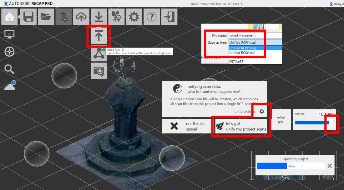
The image above shows the export of a portion of the quadrangle monument scans being exported to a unified RCS file.
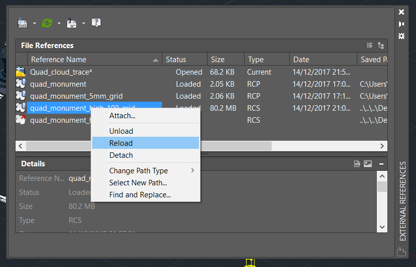
This can be attached to an AutoCAD drawing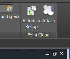 – the attachment procedure is the same as attaching an image file or an externally referenced drawing file XREF, XREF is the command you use to control display of your point clouds.
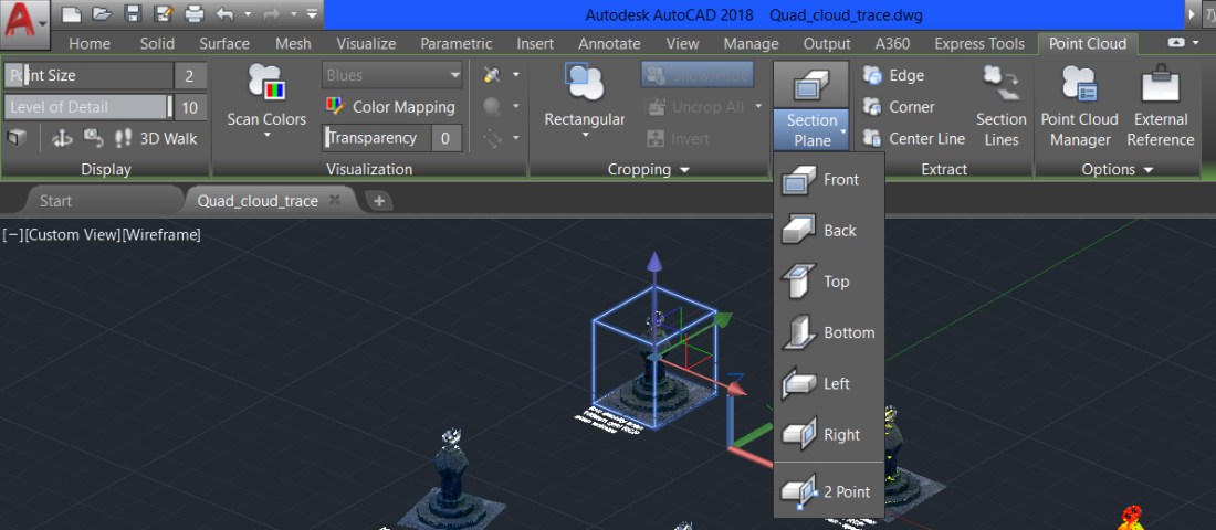
There are many tools available for working with point clouds – sectioning tools can help generate profiles to assist with modelling.
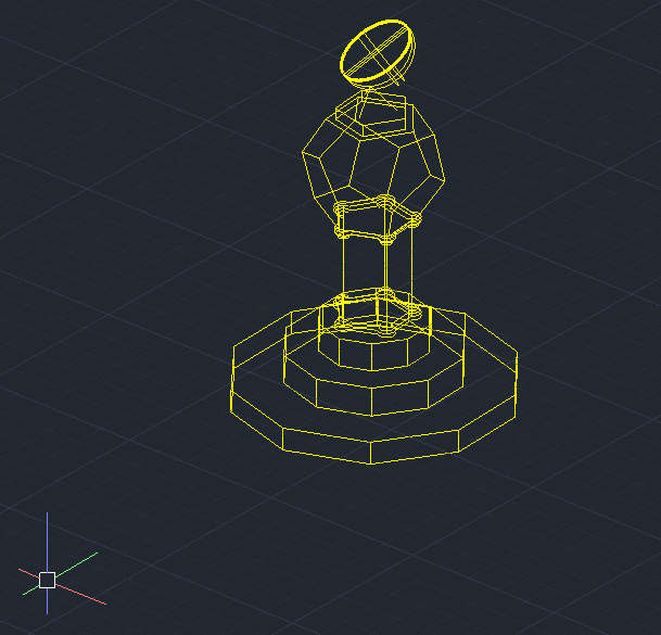
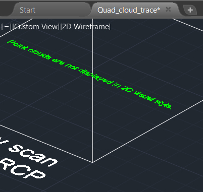
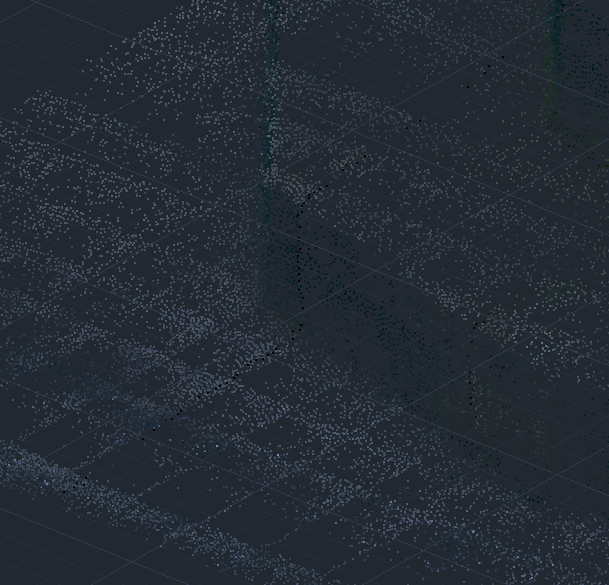
It may seem a bit bizarre but you must chose a viewport display mode that is NOT the 2D wireframe one – otherwise you will get this showing up where your point cloud should be.

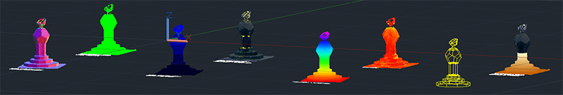
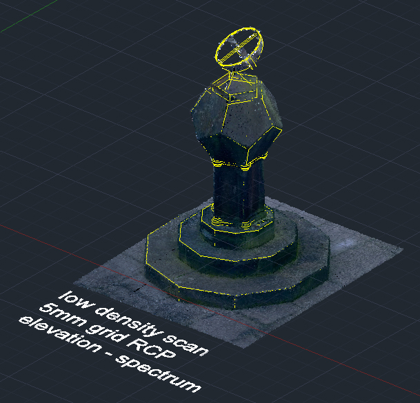
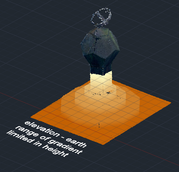
Below are some of the display modes you can set the point cloud as – ‘elevation’ is especially useful to help you discern where you are on the scan. Drawing over the scan is relatively easy – the points can be picked so long as you use the 3D Object Snaps (OSNAPS) – my wireframe attempt at a trace is the yellow line version BTW.


Below is a close-up
And another close-up


There is a lot of control possible with the gradients as you can see below – not just colours but number of colours, where the colours start and stop, etc.
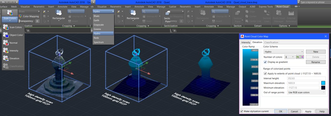
The setting is on a per cloud basis as you can see here too.